Modifying counterfeit GPS modules to make them somewhat usable
At one point I bought a couple of GPS modules that were labelled and sold as u-blox NEO-6M module breakout boards. When I finally got around to using them in a project, I discovered that they did not work properly at all and were in fact counterfeits based on the AT6558 chip with a u-blox label stuck on.
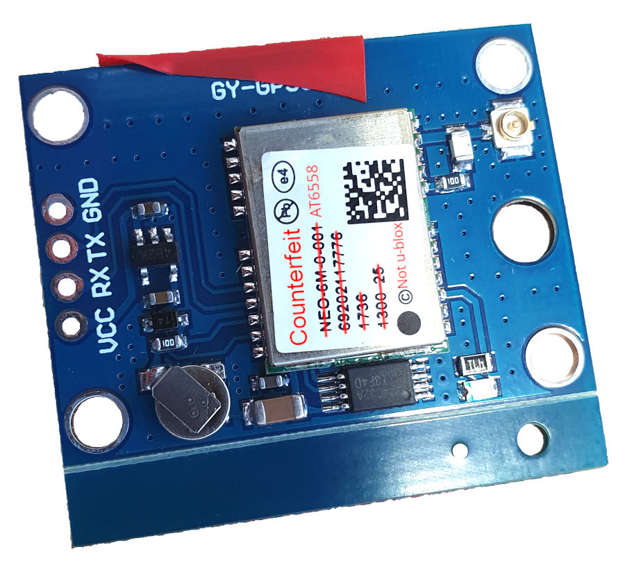
A GPS module on a breakout board that claims to be a u-blox NEO-6M module but is most certainly not. The label has been lightly edited.
The main issue in addition to not being genuine was that the modules would only start up and send data out their serial ports with the antenna disconnected. With the antenna attached, the module would enter a reset state and refuse to do anything. In addition to providing several methods to identify counterfeit units, this thread offers a hint as to why the reset occurs; the substituted modules are almost, but not quite pin-compatible with the NEO-6M-based parts that the breakout boards are intended for. The thread also hints that the counterfeit is or is close to a VK1612U7M3 module, of which sections of a data sheet are available here.
Electrical differences between the counterfeit and genuine modules
The schematic of the breakout board and the reference design in the VK1612U7M3 data sheet are both available to be compared. Because the counterfeit module’s behaviour varies with the antenna’s connection, this is the first place to look (highlighted in green on the schematics below).
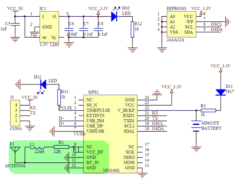
The schematic used in the breakout boards intended for use with the genuine modules. Image source: CNX Software
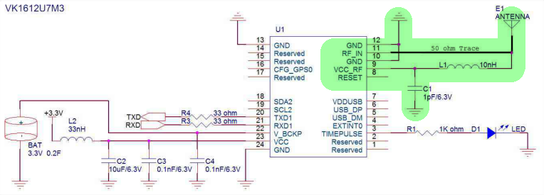
The reference schematic for VK1612U7M3 modules that use the AT6558 chip. Image source: docin.com
For both designs, pin 9 of the module (VCC_RF) provides power to an amplifier built into the antenna through a low pass filter. This filter comprises L2 and R2 in the breakout board and L1 and C1 in the reference schematic. The radio signal is received on pin 11 (RF_IN). The NEO-6M hardware integration manual specifies that pin 8 (NC) is a reset pin and must be connected to pin 9 under normal conditions. Whilst the VK1612U7M3 data sheet specifies that pin 8 is also a reset pin, it instructs that it be left open under normal conditions. My hypothesis is that in the counterfeit module the load from the antenna amplifier pulls down the voltage provided by pin 9, also pulling down pin 8 because it is connected. This causes the module to be held in the reset state. When there is no antenna and load pulling pins 8 and 9 down, the voltage is high enough for the module to start up and run.
To test this hypothesis, I removed R2 (breakout board numbering) and was able to get the module to start up with the antenna connected. Because the antenna wasn’t getting any power, the module struggled to find any satellites at all.
Modifying the breakout board
Based on the layout of the breakout board, the approach taken was to cut the connection between pins 8 and 9 of the GPS module and relocate R2 to connect with pin 9, shown on the schematic below:

The modified schematic showing the track cut between pins 8 and 9 and R2 reconnected to pin 9 to suit the AT6558 chip.
The track layout on the breakout board around the antenna is relatively close to the arrangement used in the schematic:

A not to scale diagram showing the tracks and layout for components relating to the antenna on the breakout board. Of note is the track connecting pins 8 and 9 of the GPS module what runs under the module itself.
Unfortunately, cutting the connection between pins 8 and 9 is easier said than done as the track between the pins runs under the module itself. To do this, I ended up using a hot air gun to desolder the module and cut the track with a knife before soldering the module back down. It may be possible to carefully drill out the castellated pad of pin 8 to break the connection without having to desolder the entire module, but this has not been tested.
The next step was to desolder R2 and move it across so that it connected one end of L2 to pin 9 only. Solder was used to bridge the gaps between the pins and components, shown in the photographs below:
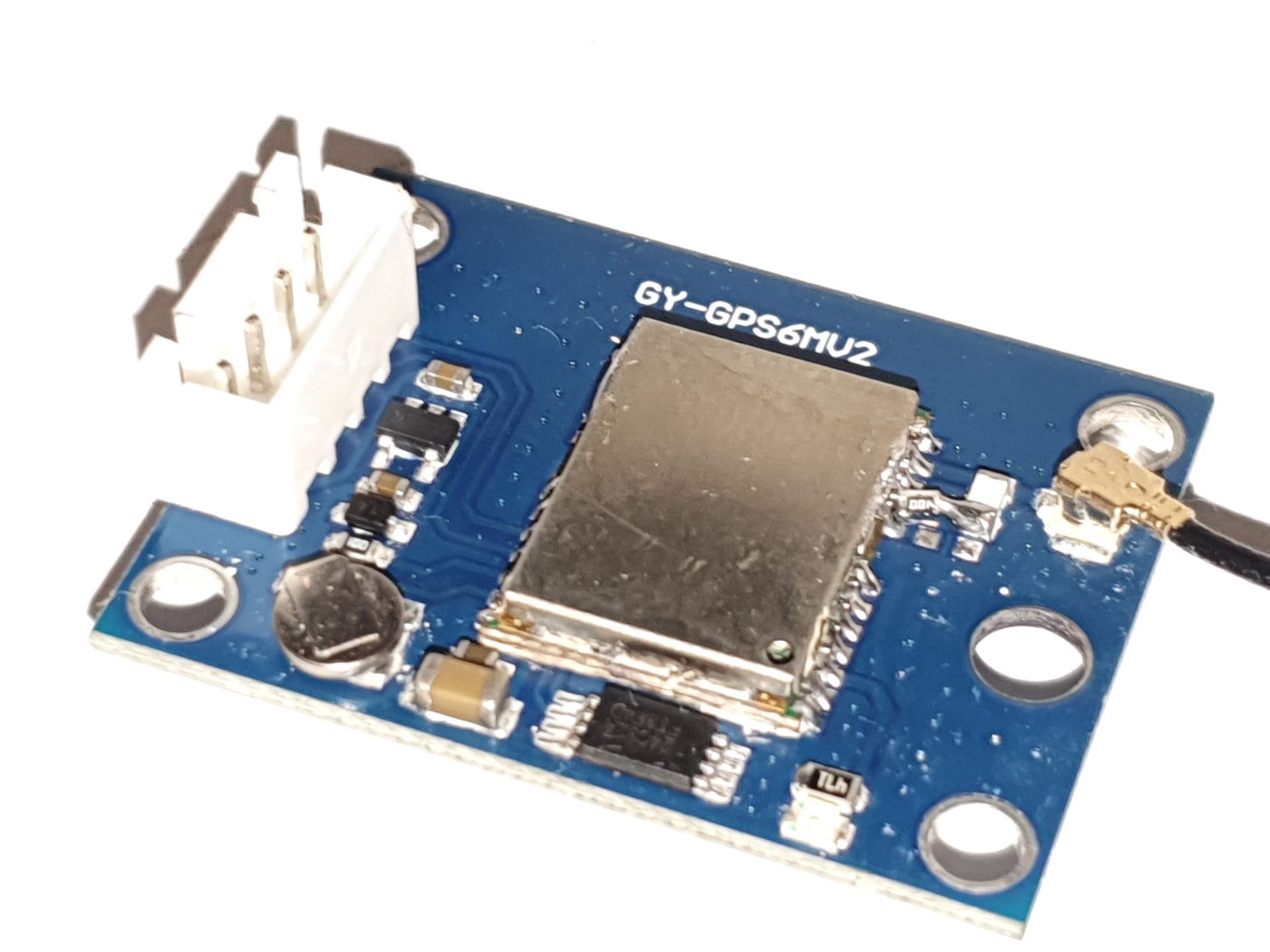
A photograph of the breakout board modified to suit the counterfeit GPS module.
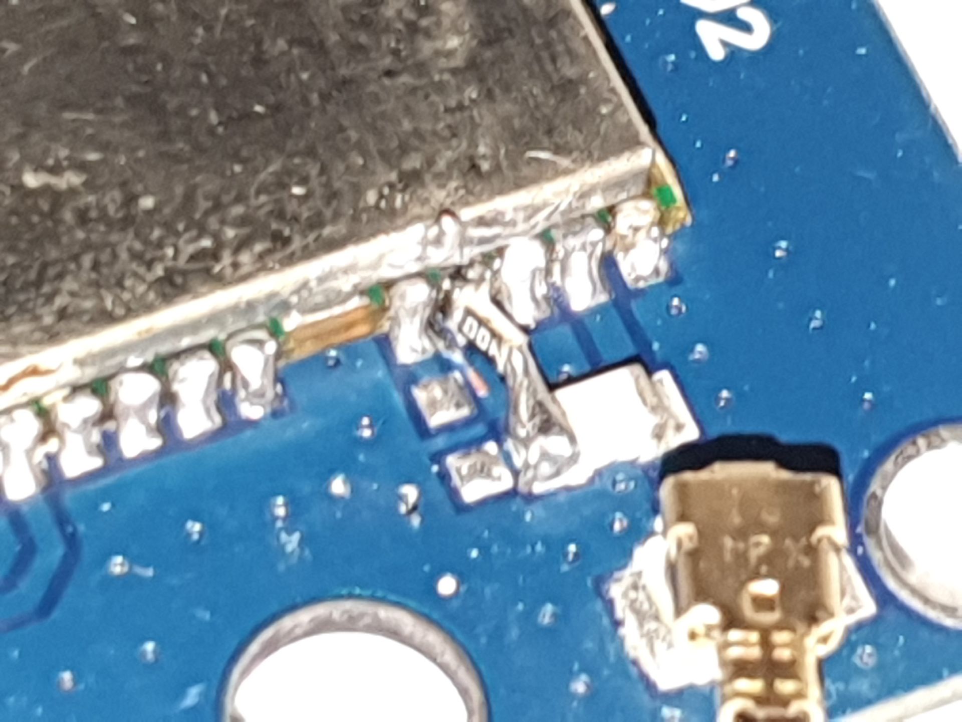
A close up of the repositioned resistor that is connected and held in place using moderately long solder bridges. Some scratch marks from cutting the track under the GPS module can also be seen.
With this completed, the board was cleaned of flux used in the process and tested. Performance, startup speed and the number of satellites in view at a time seemed quite reasonable for a cheap GPS module and were sufficient for use in the project.
Remaining issues
Whilst the GPS module now works and can see satellites and calculate position and the time, it has a number of drawbacks compared to the genuine part including:
- Desoldering the GPS module to access the tracks under it comes with a level of risk. I managed to destroy one module by blowing the components off it with the hot air gun.
- I have not been able to get any response to sending commands to the module over serial. This means I am stuck with the default settings (1Hz update rates, 9600 baud, default / no filtering on the NMEA strings sent out, …) and enter any low power or other operating modes.
- The modifications to the breakout board and deviations from the VK1612U7M3 reference schematic may hamper radio performance and compliance with various radio frequency emissions standards.
- It goes without saying, but there are no guarantees of reliability or quality when it comes to counterfeit parts. Do not use this in mission critical applications!!!
One minor advantage of the AT6558 chip included in the counterfeit over the NEO-6M is that it supports the Chinese BeiDou system in addition to the American GPS system, potentially improving accuracy and reliability.
Conclusion
These modifications were a useful workaround when I needed a GPS module in a hurry and only had these on hand. It would be greatly preferable to use a genuine module - or at least one that is actually the part it says it is on the label - to avoid having to go through this process. The NEO-6M modules themselves are getting quite long in the tooth and more modern modules may have improved capabilities and be easier to find from reputable sources.